12.7.1 General
Different investigations of the failed visor attachments and closely related items were performed. They include detailed studies of recovered parts from the actual installation, strength analysis and laboratory tests. Components retrieved from the near-sister ship DIANA II were investigated for comparison. This section contains a brief summary of the reports included in the Supplement. A conclusive analysis of the visor attachments' strength is given in Chapter 15.
 Materials of recovered parts were identified by analysing their constituent chemical elements and with mechanical, hardness, tensile and impact testing as appropriate to establish strength and basic standard cold brittleness. The deformed visor lug of the bottom lock was measured for estimating the type of overload and the load level to which it would have been subjected comparing it with deformation-load interdependencies obtained through full-size model testing. The stiffness of the whole visor was measured to assess its effects on the wave load distribution to the various attachment points. Materials of recovered parts were identified by analysing their constituent chemical elements and with mechanical, hardness, tensile and impact testing as appropriate to establish strength and basic standard cold brittleness. The deformed visor lug of the bottom lock was measured for estimating the type of overload and the load level to which it would have been subjected comparing it with deformation-load interdependencies obtained through full-size model testing. The stiffness of the whole visor was measured to assess its effects on the wave load distribution to the various attachment points.
Analytical and finite element calculations were used for estimating the strength of the different attachments taking account of their actual geometry and material. The welds as well as any deficiencies found were assessed where pertinent.
The combined strength of the visor attachment system was estimated with balanced reaction load calculations using variation of external loads. In the calculations, either parameters describing load sharing and/or attachment site stiffness were used, or attachment loads were assigned by using parametric variation of the wave load centre of action in relation to the positions of the attachments.
The paint layers on the surface of the bottom lock were investigated in some detail to estimate approximately the age of the attachment.
12.7.2 Material identifications and microscopical observations
Materials used for the various attachments were identified as given in Table 12.6. The table also defines the tests applied and includes remarks on main observations.
Table 12.6 Summary of materials used for the attachments and tests applied.
| | Main investi-
gation | Additional tests | Other | Probable Material ID & other remarks |
| Bottom lock |
| Visor lug | Dimensions | Hardness HBS 10/3000 | | Mild steel. Stretched about 6 mm by load exceeding limit for general yield. |
| Broken lugs and weld joint of forepeak structure. | Tensile test | Hardness HV 10 | Micro-
scopy | Lugs: mild steel. Weld: high-strength steel.Some cracking in welds. |
| Locking bolt from DIANA II. | Hardness and dimensional measure-
ments. | HBS 5/250 and HRB | | 230 - 235 HBS 5/250
96 - 98 HRB
(UTS = 760 - 785 MPa) |
| Visor lug from DIANA II. | Hardness and dimensional measure-
ments. | Hardness HBS 10/3000 | | Mild steel. Stretched similar to the ESTONIA lug. |
| Side locks |
| Visor aft plating | Tensile test. Through thickness tensile test. Test section 12x12 mm2, length 8 mm. | Thickness 8 mm | | Mild steel. No detrimental effect of delamination on strength - material of high quality. |
| Horizontal stringer | Tensile test | Thickness 10 mm | Chemical analysis | Mild steel |
| Vertical stiffener | | Thickn. 20 mm
Weld a appr. 5 mm | Chemical analysis | Mild steel |
| Hinges |
| Lug plates | Tensile test Impact test | | | Mild steel Grade E (TKV28<-40°C) |
| Bearing bushing | Chemical analysis | | | |
| Bushing weld joint | Tensile test of 14 mm slice including bushing, weld joint and lug plate. | | | Fracture dominantly by 6.4 mm wide shear at weld joint, UFL 0.12 MN, USS appr. 717 MPa |
| Lifting cylinder attachments |
| Hinge arm lug | Hardness testing | | | Mild steel |
| Deck 3 plate | Impact testing | | Fracture micro-
scopy | Grade C (TKV28<0°C) Fatigue and cold brittleness cracking. |
| Hardness measurements: HBS 10/3000 is Brinell hardness measured using steel ball of 10 mm diameter and 3000 kg mass, HRB is Rockwell B-hardness and HV is Vickers pyramid hardness. Strength values: UTS=ultimate tensile strength, USS=ultimate shear strength and UFL=ultimate fracture load. Cold brittleness characteristic TKV28=temperature for reaching 28 J impact toughness using the Charpy-V method. |
Optical and electron microscopy were used to find signs of cracking and to identify the character of various fractures. Particularly the visor actuator mounting platforms had fatigue cracks of marked significance for ultimate strength. On the port side about half of the perimeter cross-section through deck 3 had developed fatigue cracks before the accident. Some repair welding had been undertaken.
12.7.3 Investigations of the attachments
Bottom lock attachment and visor lug
Specimens of the actual bottom lock attachment lugs recovered from the wreck were tested with regard to material properties. The material was regular mild steel with a yield strength of about 240 MPa and an ultimate tensile strength of about 410 MPa. The lug fractures showed patterns typical of good-quality ductile plate that failed due to local overload. Some branched cracks that were small compared to the size of the lugs were detected close to the primary fracture surfaces of the welds between the plates and the locking bolt housing. These cracks may have developed under normal operation due to the cyclic nature of operating loads or e.g. during the sequence leading to failure of the bottom lock. The separate effect of these small cracks has been impossible to quantify but their combined effect on the load-carrying capacity of the lock was apparently small due to the ductility of the plate material.
The fracture surfaces of all three bottom lock attachment lugs were examined by optical stereo microscope and by scanning electron microscope. It was concluded that all the fracture surfaces had a ductile character and that the failure types were the result of overload. It was also noted that the fillet welds attaching the housing and the lock bushing showed signs of poor fusion and lack of penetration.
Hardness was measured on welds and base plate of the lug assembly on the forepeak deck to estimate the strength of the weld. The hardness of the bushing-lug weld material was HV10 = 270 - 275, which translates to an ultimate tensile strength of 865 MPa (DIN 50150) for the weld material. The hardness of the lug plates was HV10 = 128 - 150, which correlates well with the ultimate strength of 417 MPa measured. The weld material and the adjacent heat-affected zone were thus significantly stronger than the material of the plates that had been joined together.
The failure strength of each attachment lug was calculated based on the material properties found in the testing and the actual cross-section of each fracture surface.
The welds contribute significantly to the strength of the lug assembly. A large variation in the path of the weld fracture made measurements of the weld size contributing to strength very tedious. The most unambiguous value for the strength of the bottom lock was obtained by analysing the deformations of the mating lug. A transfer calculation developed as part of the investigation served to estimate the contribution from the welds. The calculation indicates that the effective size of the weld joint could have been around 3 mm. This was also observed, although the actual weld joint was quite irregular.
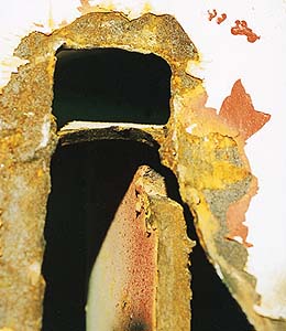
The mating visor lug was bent and elongated (Figures 12.17 and 12.18). Hardness testing showed the plate material to be most probably mild steel and similar to the material of the hinge plate. The aft or eye end of the mating lug had been elongated and bent to starboard. By analysing the shape of the hole and lug rim it was concluded that the original dimensions of the lug aft end had conformed to drawing. In its retrieved condition the aft end eye ligament had the designed dimension of 47.5 mm suggesting no damage by wear to this side of the eye.
Figure 12.17 The visor lug for the bottom lock with a disc of the same diameter as the bolt inserted.
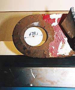
Figure 12.18 Dimensions of the visor lug after the accident.
Comparison with tests with several mock-ups of full or subsize scale showed that the lug had been stretched, most probably prior to the bending. The tests indicate that permanent yielding in the authentic lug started at a tensile load of about 0.5 MN. The measured net stretching of around 6 mm may have occurred under a load of about 1.5 MN. In addition wear of up to 2 mm was observed on the stem (forward) side of the eye suggesting leaning of the visor against the locking bolt. The dimensional analysis indicated that the initial length of the lug stem was 3 mm less than the drawing dimension.
Load capacity of the forepeak deck lug assembly was estimated by calculations based on two different methods. One used the deformation energy principle employing the assumption of a perfectly stiff locking bolt. The other was a simplistic strength estimate based on the assumption of the weld carrying its ultimate strength in shear of the simply sheared part of the failure path cross-section and the projection of the weld cross-section actually subjected to mixed shear and tension. Both methods included parameters that needed quantification by test results.
It was impossible to determine whether usage-related damage - e.g. fatigue cracks - had reduced the strength of the bottom lock. No fatigue cracks were found in the forepeak deck lugs, but cracks could have existed in the welds prior to failure. Recognising this it was estimated that if half or more of the weld joint related load-carrying capacity had been lost, the strength of the bottom lock would have been about 0.8 MN at its lowest as demonstrated by testing at the Technical University of Hamburg (see 15.3). In this case, logically the 1.5 MN load that had sometimes acted to stretch the visor lug must have actually occurred earlier. This load must then have initiated the damage to the welds, and the original strength of the bottom lock would have been more than about 1.5 MN. It has also been calculated that the strength of the bottom lock could theoretically not have exceeded 1.8 MN, the estimated load needed to break the visor lug by shearing the lug tip, as indicated by testing at the Technical University of Hamburg.
Bottom lock details from the DIANA II with a similar visor locking installation as in the ESTONIA were also investigated. They included the visor lug and the bolt. The bolt material was identified to be of a higher strength grade than the lug plate. The visor lug material was identified as mild steel. The aft or eye end had stretched apparently by overloading up to several millimetres in similitude with the visor lug of the ESTONIA. The lug eye and the bolt had several millimetres more wear on their stem sides due to leaning of the visor onto the locking bolt and the rubbing that had occurred.
Paint layer analysis
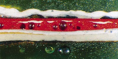
Samples of paint coatings were analysed from the forepeak deck starboard lug (Figure 12.19) and from the visor lug for the bottom lock (Figure 12.20). The paint system consisted of several paint layers, from 4 to 7 in the samples from the forepeak deck lug and 8 layers in the sample from the visor lug. Many of the layers were discontinuous. The chemical compositions of the paint layers indicate that both lugs had similar light brown �varnish� and grey primer. The yellowish primer closest to the steel in the visor lug was not detected in the paint samples from the forepeak deck lug. White and red paint stains found between the topmost layers and on the surface of the forepeak deck lug had similar chemical composition as the red and white paint layers in the sample from the visor lug. It thus seems evident that the whole bottom lock was old and dated at least to the early history of the ship. The detailed reports of the paint systems investigations are included in the Supplement.
Figure 12.19 Cross-section of a paint sample from the forepeak deck starboard lug.
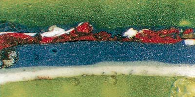
Figure 12.20 Cross-section of the paint sample from the visor lug for the bottom lock.
Side locks
The side locking lugs with part of the visor plating remain on the wreck, still attached to the locking bolts. Thus the only parts possible to investigate from the actual installation were from the visor structure at the original position of the side locking lugs.
The bulkhead plating in the areas where the lugs for the side locks had been mounted were investigated. It was concluded that the lugs had separated by shearing of the horizontal stringer plate, the vertical stiffener at the related weld and through the visor aft plating. Some delamination of the aft plating material was observed. The shear surface in the aft or bulkhead plating had marks of heavy rubbing.
The attachment arrangement for the side locking lugs was investigated in detail and their strength was evaluated with both full scale mock-up tests and computer modelling and calculations. A loading direction commensurate with visor release by rotation either about the hinge axis or the stem post without twisting or yawing was primarily considered. Thus only tension at 38� to the visor aft plating was considered in the tests, but other directions were assessed by calculation.
Four full-scale mock-up tests were made with various degrees of rigidity in the plate membrane and stiffener plates onto which the lock lug had been welded (Figure 12.21). In the relevant test cases the failures were very similar to the authentic failures, i.e. tearing of the aft plating. Membrane and stiffener stiffness had a significant effect on the strength of the lug attachment model. The test which was deemed to be most representative gave a failure load of the lug attachment of about 1.8 MN. Tensile tests of authentic plates were made. A welding defect was noted on the authentic port side installation of the horizontal stringer (Figures 12.22 and 12.23). This defect was estimated to reduce the strength to 1.2 MN, account also taken of the differences between the test mock-up materials and the authentic plates. Similarly, the strength of the starboard locking site was estimated to be 1.6 MN. The failures took place by shear of the stringer plate first and then in the plating around the fillet weld of the lug, leaving similar fractures to that noted in the actual failure.
Figure 12.21 Full-scale mock-up test of the side locking lug structure.
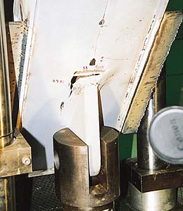
Figure 12.22 Failure at port side lug location at horizontal stringer.
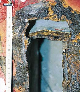
Figure 12.23 Failure at starboard side lug location at horizontal stringer.
Calculations made parallel to the testing confirmed the test results. A numerical estimation by the finite element method, using the actual material stress strain curve data and partial visor structure, gave an ultimate collapse load level of 1.6 MN. The failure load of the lug attachment would have been lower if the acting force had been parallel to the bulkhead plating, e.g. if the visor had been lifted vertically instead of rotated around its end points.
Hinges
Fracture surfaces of the hinge beams were partially investigated in the same way as the bottom locking lugs. The studied failures were of ductile character and signs of fatigue were not seen. A fracture was observed in one sample, penetrating through the weld. The gap inside the weld was filled with magnetite, indicating slow corrosion in an atmosphere with low oxygen content. This was taken as indication that the crack had existed for a long time before the accident, allowing some moisture to penetrate.
In subsequent studies it was also confirmed that the welds at the hinge bushings had extensive cracking in the roots and that these cracks had to some extent progressed under fatigue conditions. It was concluded that the failure of the rims of the hinge beam side plates started with ductile failure of the lower part of the periphery as a result of overload, followed by failure of the upper part due to bending as evidenced by lateral contraction of the tensile or inner side and lateral expansion of the outer or compression side. Microscopic features displayed ductile character.
The parts of the hinge lug plate rim fractures that were flat fractures called for evaluation of their character also with respect to material toughness or cold brittleness. For this reason impact toughness specimens from the hinge beam side plate were tested. The values indicate high toughness and thus no tendency to reduced strength by brittleness.
The ultimate failure strength of the plate material was found by standard tensile testing to be 450 - 460 MPa, i.e. mild steel.
Two tensile tests were also carried out on the weld joints using a slice of the bearing support bushing-hinge plate rim. Test specimens were prepared from segments of one recovered hinge bushing with parts of the outer rim of the visor hinge beam side plate attached to it. These gave a failure load of 0.12 MN for the tested length (14 mm) of actual fillet welds. The failure occurred dominantly in shear with an ultimate shear stress of about 700 MPa. Thus, the weld material had a very high strength.
The strength of a complete hinge was calculated on the basis of the test results for the strong tensile aftward direction of 21� down from horizontal and aft, and the weak shearing direction of 21� forward from down. The strong direction is assumed to coincide with the line bisecting the angle of the hinge beam in its aft part and the weak direction is normal to this.
The strength for one hinge was estimated to be 4.6 MN for the weld joint shear fracture of bushing to lug weld and an additional 2.3 MN for the lug rim at yielding load if this addition applied in case of close clearance between the lug and the bushing.
A previously observed crack in the downward segment of the hinge bushing weld joints that was reported to the Commission was taken into account in the strength estimates. Root cracking detected in the forward segments was not accounted for separately and may have lowered the actual strength from the values given.
Actuator attachments
The attachments of opening actuators had secondary influence on the release of the visor. Material identification and fractography was undertaken for completeness of the investigation. It was found that the mounting platform at the bottom of the port actuator on deck 3 had cracking significant for the strength of the platform. Deck 3 plate had finally fractured by the cold brittleness mechanism - cleavage. One lug of four on the hinge beams - providing for the upper attachment of the actuators - was identified by hardness testing to be mild steel.
Attachment system
The combined strength of the visor attachment system was estimated by calculations covering strength estimates for the individual attachment components and studies of the load distribution within the system.
A system of five attachments is statically indeterminate and reaction forces will depend on the stiffness both globally and locally at the attachments. Also misalignment and play between bolts and lugs at the locks may influence the load distribution. It was thus considered to be of little value to make a complete numerical analysis of the whole visor. Instead the failure load levels for different assumed load or stiffness distributions were assessed. The results of the analyses are therefore indicative rather than conclusive.
The global stiffness of the visor was measured in its upside-down, stored position as supported at the hinge beams. By adding a weight at one hinge beam and lifting at the other, a vertical displacement compliance of approximately 25 mm /1 MN lifting load was obtained. The visor was thus moderately flexible across its centre line in relation to the expected loads of several MN. Each side of the visor is a box structure and is estimated to be fairly stiff compared to the visor's side-to-side distortion flexibility. The lower part of the structure holding the bottom locking lug is also flexible compared to the sides.
Three different calculation schemes using principles of statics including assumed load sharing by the locking sites were formulated for estimating the load levels and directions at the attachments from an applied bow load level and direction. One of the methods varied load sharing systematically between the attachments, another varied the relative stiffness of the attachment points and the third varied the location of the wave load centre of action. Load component ratios obtained from SSPA's model tests were used in estimating the total load needed to break the visor attachments. The results indicate that the port side lock appears to have broken in bow sea at a lower level than the load required to break the next attachment. It could not be determined which of the remaining attachments, the bottom lock or the port hinge, would break second as the uncertainty in finding the strength level of the hinge was quite large. Estimated failure load levels in bow sea were significantly lower than those in head sea.
Observed damage to the visor indicates that the hinge may have broken second, allowing subsequent rising of the visor with damage caused to the port locating horn recess as well as a marked downward bending of the mating bottom lock lug on the visor. |