8.6.3 The visor hinge arrangement
The visor deck hinge fittings were found during the ROV and diver surveys to be intact except for pounding marks on the side plates, essentially at their upper parts, above the centre of the hinges (Figure 8.16). The hinge shafts had almost fully fallen out from the housings and the shaft starboard ends were resting on the deck railing. The starboard side bushing of the port hinge was still attached to the shaft as Figure 8.20 shows.
 All four hinge bushing housings had separated from the side plates of the hinge arms. The failure had generally taken place at the fillet welds and the rim of the lug, surrounding the aftward facing part of the housing. The welds had failed generally in the fusion zones between either the weld beads and the housing or the bead and the side plates. Figures 8.21, 8.22, 8.23 and 8.24 show port and starboard failed hinge beam lugs. All four hinge bushing housings had separated from the side plates of the hinge arms. The failure had generally taken place at the fillet welds and the rim of the lug, surrounding the aftward facing part of the housing. The welds had failed generally in the fusion zones between either the weld beads and the housing or the bead and the side plates. Figures 8.21, 8.22, 8.23 and 8.24 show port and starboard failed hinge beam lugs.
Figure 8.21 Failed visor port hinge lugs.
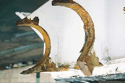
Figure 8.22 Failed port lug of visor port hinge.
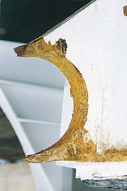
Figure 8.23 Failed port lug of visor starboard hinge.
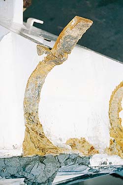
Figure 8.24 Failed starboard lug of starboard hinge.
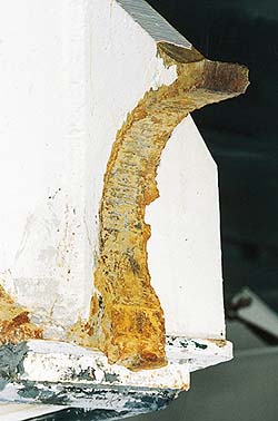
Figure 8.25 Scratch marks on the piston rod of the visor port side opening actuator.
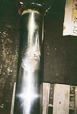
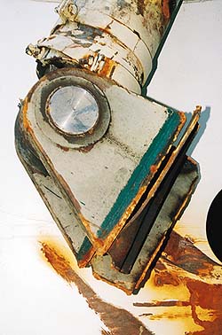
Figure 8.26 The bottom end of the visor port side opening actuator.
One bushing housing, most probably the inner starboard one, was recovered by the divers and has been investigated in detail. The hinge beam side plates were likewise removed from the visor and have been investigated in detail.
8.6.4 The visor actuating arrangement
The failure of the visor actuating mechanism was caused by failure of the bottom mounting platform of the port side actuator and full extension of the starboard side actuator, whereupon the mounting platform was pulled out of the hull.
The port side actuator was found closed but showed signs of having been extended by about 0.4 m, indicated by scratch marks on the piston rod (Figure 8.25), which remained straight. The bottom mounting platform consisted of a reinforced section of deck 3, surrounded by vertical longitudinal and transverse structural members. Two bulb bars were arranged below the platform as part of deck 3 structure. One of these bulb bars showed repair of a previous crack, close to its end attachment to the vertical bulkhead. The platform was pulled out of the hull by shearing of the plating and failure of welds around the entire platform, sized about 600 x 450 mm (Figure 8.26). The bulb bars separated from the adjacent bulkheads because of weld failure. The old repair weld had not failed. The shear surfaces show indications of old cracks along a considerable part of their length.
The starboard side actuator initially failed because of failure of the hydraulic seals around the piston rod, allowing the rod to become fully extended. The piston rod was bent in the forward direction by about 30 degrees. The bottom platform of the mounting was eventually pulled out of the hull due to shearing of the platform and failure of the welds. A tongue of the forward bulkhead at the mounting platform was pulled out of the hull together with the platform.
The lugs for connecting the actuators to the visor deck beams showed indentations and scoring on the forward and starboard side faces (Figure 8.9). The sealing arrangement around the deck openings for the actuators, consisting of rubber seals supported by steel flat bars, was compressed over most of the surface and some paint marks showed that the hinge arms had been in limited contact with the deck plating.
8.6.5 The ramp attachment and locking devices
The two port side hinges at the bottom of the ramp had failed because of tension fracture of the ramp-mounted lugs.
The mounting of the pins for the upper locking hooks was heavily twisted. The locking hooks could not be inspected in detail but were confirmed to be in locked position. The hydraulic actuators were in extended (locked) position.
Three of the four side locking bolts were in their extended position and the mating boxes on the ramp side beams had been ripped open. The port side lower locking bolt was only partly extended and its mating box was undamaged.
8.6.6 The visor and ramp indicating devices
The magnetic-type position sensors for the bottom lock were not in position on their mounting bracket according to pictures taken during the ROV and diving investigations. The electric cabling that had been part of the sensor installation and the ends of the cables were visible in the area. The mounting bracket for the sensors appeared to be intact or possibly bent slightly aft. No other signs of any mechanical action could be seen on the bracket. The 12-millimetre-diameter bolt holes for the originally installed mechanical switches were empty. It is not fully clear how the magnetic sensors had been installed on the bracket.
The magnet which was part of the bottom lock position indicator was after the accident visible on its mounting bracket in the locking bolt. According to information obtained from the electrical engineer who installed the magnetic sensors and the magnet in the mid-1980s they were of the Siemens 3SE6-type.
The indicating sensors for the side locking lugs could not be inspected but the damage picture indicates that the locking devices were in fully closed position.
Continues... |